Land Rover Defender: Click & Play Tablet Holder - Samsung
CLICK & PLAY TABLET HOLDER - SAMSUNG - PART NUMBER: VPLRS0394
REMOVAL AND INSTALLATION
WARNING: Accessories which are not correctly installed can be dangerous. Read the instructions carefully prior to installation. Comply with instructions at all times. If in doubt, contact your nearest approved retailer.
CAUTIONS:
- Take suitable care not to damage the click & play tablet holder if the rear seats are folded down.
- A protective film must be fitted to the tablet before installing it to the click & play tablet holder.
- When not in use the click & play tablet holder should be stored in the luggage compartment.
NOTE: If your vehicle seats are fitted with an integrated backrest base unit as illustrated, you do not need the click & go system base unit, item VPLRS0388.
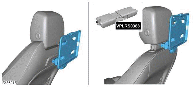
INSTALLATION
1.

If your vehicle seats are fitted with an integrated backrest click and go base unit, raise and hold open the flap while installing the click & play tablet holder.
2.
NOTES:
- The click & play tablet holder should be fitted with the button facing the right hand side of the vehicle as illustrated.
- Listen for an audible click. This confirms the click & play tablet holder is locked into the base unit.
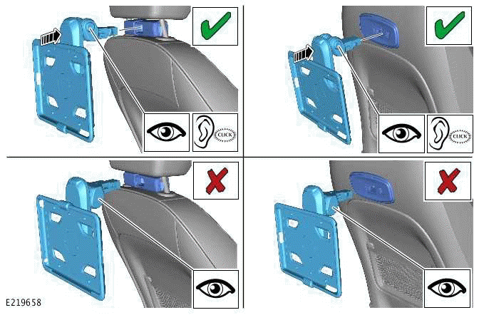
Push the click & play tablet holder fully into position.
3.
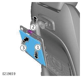
Installing the tablet on to the click & play tablet holder.
- Position the tablet.
- Lift the securing clip.
- Lock the tablet into position.
4.
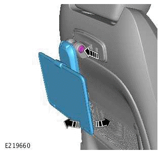
Depress the button to pivot the tablet forwards and backwards.
5.
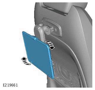
Rotate the tablet if necessary.
6.
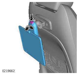
Depress the button to pivot the arm as necessary.
REMOVAL
1.
.png)
Removing the tablet from the tablet holder.
- Lift the securing clip.
- Pull tablet forward.
- Remove the tablet.
2.
.png)
Removing the tablet holder from the base unit.
- Depress the buttons.
- Pull out the click & play tablet holder.

