
Land Rover Defender: Crankshaft Pulley - Ingenium I4 2.0l Petrol
REMOVAL AND INSTALLATION
SPECIAL TOOL(S)
JLR-303-1628
Remover/Installer, Front Crankshaft Seal
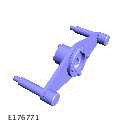
JLR-303-1630
Locking Tool, Crankshaft Pulley
PART(S)
REMOVAL
NOTE:
- This procedure contains some variation in the illustrations depending on the vehicle specification, but the essential information is always correct.
- This procedure contains illustrations showing certain components removed to provide extra clarity.
1. Raise and support the vehicle on a suitable 2 post lift.
2. Disconnect the startup battery ground cable.
3. Remove the accessory drive belt.
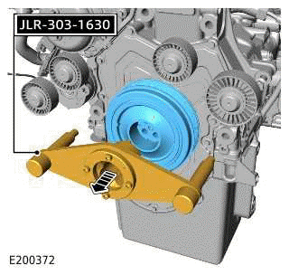
4.
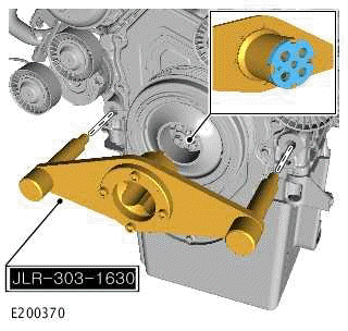
Install the special tool as illustrated.
Special Tool(s): JLR-303-1630
5.
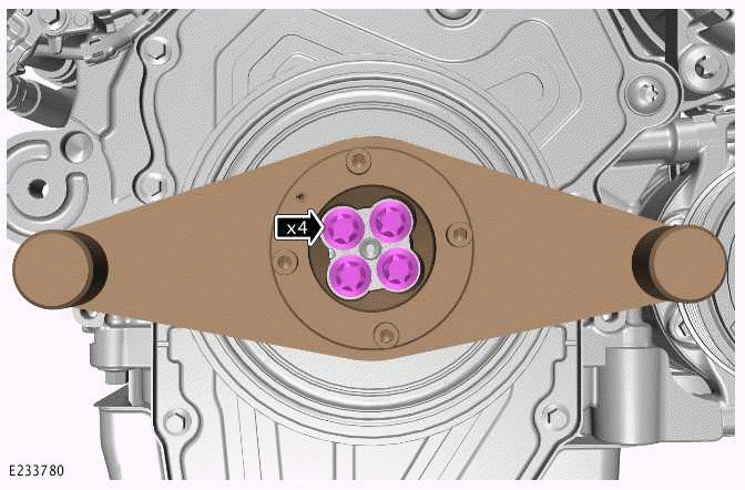
Remove and discard the 4 bolts.
6.
CAUTIONS:
- Only rotate the crankshaft clockwise.
- Make sure the special tool is correctly aligned.
- Remove the special tool.
Special Tool(s): JLR-303-1630
- Remove the crankshaft pulley.
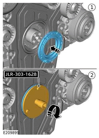
7.

- Install the special tool.
Special Tool(s): JLR-303-1628
- Use the special tool to rotate the crankshaft front seal 35º in a counter-clockwise direction.
- Discard the crankshaft front seal.
INSTALLATION
1.
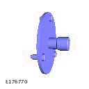
- Install a new crankshaft front seal to the special tool.
Renew Part: Crankshaft front oil seal Quantity: 1.
- Use the special tool to install the crankshaft front seal.
- Tighten the crankshaft front seal.
Torque: 26Nm
2.
CAUTION: Make sure that the crankshaft pulley is correctly located on the dowel.
- Install the crankshaft pulley.
- Install the special tool.
Special Tool(s): JLR-303-1630
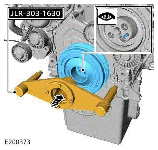
3.

- Before installing the new crankshaft pulley bolts check the length of the threads as illustrated.
- The new bolts must be 48mm in length.
4.
- Working in a diagonal sequence, install and tighten the 4 new crankshaft
pulley bolts.
Renew Part: Crankshaft pulley bolts Quantity: 4.
Torque
- Stage1: 37Nm
- Stage2: 90º
5. Remove the special tool.
Special Tool(s): JLR-303-1630
6. Install the accessory drive belt.
7. Connect the startup battery ground cable.
READ NEXT:
 Crankshaft Rear Seal - Ingenium I4 2.0l Petrol
REMOVAL AND INSTALLATION
SPECIAL TOOL(S)
100-012
Slide Hammer
JLR-303-1674
Installer - Rear Crankshaft Oil Seal
JLR-303-1674A
Installer - Rear Crankshaft Oil Seal
JLR-303-1712
Remover, Rear Cranks
Camshafts - Engine Set
REMOVAL AND INSTALLATION
REMOVAL
NOTE:
This procedure contains some variation in the illustrations depending
on the vehicle specification, but the
essential information is always correct.
This p
Oil Cooler - Ingenium I4 2.0l Petrol
REMOVAL AND INSTALLATION
PART(S)
REMOVAL
WARNINGS:
Be prepared to collect escaping oil.
Be prepared to collect escaping coolant.
CAUTION:
Before disconnecting any components, make sure the area i
SEE MORE:
Body Control Module/Gateway Module Assembly
REMOVAL AND INSTALLATION
GENERAL EQUIPMENT
REMOVAL
NOTES:
If a new Body Control Module/Gateway Module (BCM/GWM) is installed, a
new Remote Function Actuator
(RFA) must also be installed. This step is only required for vehicles that
are 15MY or later. This step is not
required for North Amer
Floor Console
REMOVAL AND INSTALLATION
REMOVAL
NOTE:
This procedure contains some variation in the illustrations depending
on the vehicle specification, but the
essential information is always correct.
This procedure contains illustrations showing certain components
removed to provide extra clarity.
1. D
