
Land Rover Defender: Seat Backpack
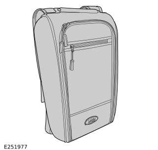
SEAT BACKPACK - PART NUMBER: VPLES0573
REMOVAL AND INSTALLATION
WARNING: Accessories which are not correctly installed can be dangerous. Read the instructions carefully prior to installation. Comply with instructions at all times. If in doubt, contact your nearest approved retailer.
NOTE: This procedure contains some variation in the illustrations depending on the vehicle specification, but the essential information is always correct.
INSTALLATION
1.
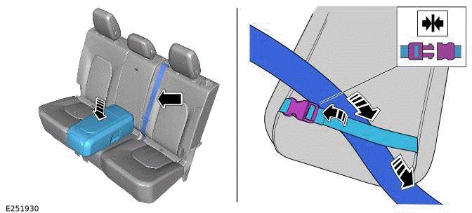
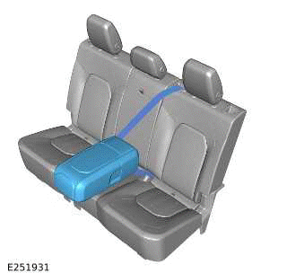
Place the seat backpack in the middle of the second row seats. Strap the seat backpack to the seats by attaching the seat backpack rear strap over the center seatbelt. Engage the second row center seatbelt to the second row center seatbelt buckle.
2.
WARNING: When using the seat backpack on the second row seats the seat backpack must be strapped to the engaged second row center seatbelt.
3.
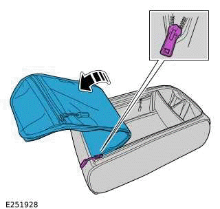
Unzip the front panel to reveal the main compartment.
4.
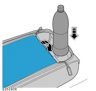
Partially unzip the front panel to use the cup holder section. Tuck the top of the front panel behind the cup holder section.
5.

When using the seat backpack outside of the vehicle then follow steps.
- Unzip the top rear section and pull out the shoulder straps.
- Unclip the rear strap and clip each shoulder strap to the adjacent part of the rear strap.
6.
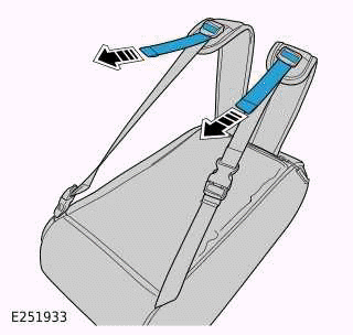
To adjust the straps pull on the part of the strap as illustrated.
READ NEXT:
 Ski Bag
SKI BAG - 110, PART NUMBER: VPLGS0166
REMOVAL AND INSTALLATION
WARNING:
Accessories which are not correctly installed can be dangerous. Read the
instructions carefully prior to
installation. Comply w
Front Treadplates
FRONT TREADPLATES - PART NUMBER: 90:
VPLES0575PVJ, VPLES0595LAA, LR131474,
LR131466, LR131475, LR131467 110: VPLES0576PVJ,
VPLES0596LAA, LR131470, LR141462, LR131471,
LR131463
REMOVAL AND INSTALLATION
Loadspace Treadplate
LOADSPACE TREADPLATE - PART NUMBER:
VPLES0572
REMOVAL AND INSTALLATION
WARNING:
Accessories which are not correctly installed can be dangerous. Read the
instructions carefully prior to
installation.
SEE MORE:
Seats - [+] 7 Seat Configuration - Component Location
COMPONENT LOCATION - 1 OF 5 - SEAT ADJUSTMENT CONTROL MODULES
NOTE:
Right Hand Drive (RHD) vehicle is shown, Left Hand Drive (LHD) vehicle is
similar.
Heating, ventilation, and air conditioning (HVAC) control module
Touch Screen (FCDIM)
Instrument Panel Cluster (IPC)
Driver Door Control Modul
Brake Pads 6 Piston Fixed Caliper
REMOVAL AND INSTALLATION
MATERIALS
GENERAL EQUIPMENT
REMOVAL
WARNINGS:
Brake pads must be renewed in axle sets only. Failure to follow this
instruction may result in braking
efficiency being impaired.
If the brake pad wear warning indicator has been activated, a new
brake pad wear sensor m
